|
PIC Microcontroller circuit board Following on from the PC based LANc controller I needed to design a circuit board that would replace my laptop and fit into the underwater housing. The solution is to use a PIC microcontroller. These chips are like a miniature PC. They have a processor, memeory and ports. The problem is how to write a program for them and then copy it into the PIC. You can either write the program in ASSEMBLER language (uphill and not user friendly), and use a freebie asssembler program downloaded off the web, or blow some money and get some software that allows you to write in BASIC. I opted for the easy way as life is too short and bought Crownhill's - Proton Development Suite. You then need a circuit board to write to the chip. There is a variety of USB and COM port versions. The COM port ones are cheap, under £10, but they only work on COM ports that provide +- 9 volts. Most laptops don't! Also make sure the programmer and software is compatible with your microcontroller. I bought a JDM2 off of Ebay. You can download PicPgm to use with it. It works really well.
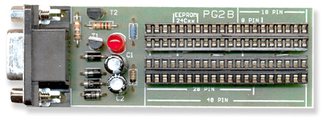
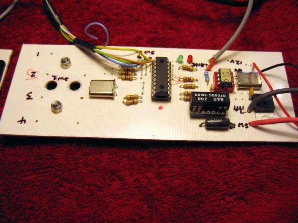
The PIC microcontroller circuit board The criterior I used to build this board was based on my experience with the PC based prototype and the number of camera functions I can control. Tony Birchley was willing to fit 8 sliding magnets to the housing which in turn would pull in the reed switches mounted on the boards, inside the housing. No holes! I chose to use the PIC16F628A controller. It has two 8 pin ports. The circuit design looks like this:
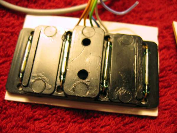
The main and second switch boards look like this:
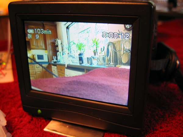
Viewfinder using an external monitor
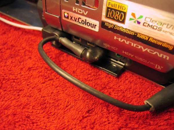
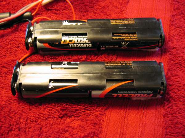
I also bought a right angle AV cable. This saves a nasty cable bend in the housing and keeps the cable short. Battery pack If you don't require a monitor the LANc board can be wired to the LANc socket jack to pick up the power from the camera.
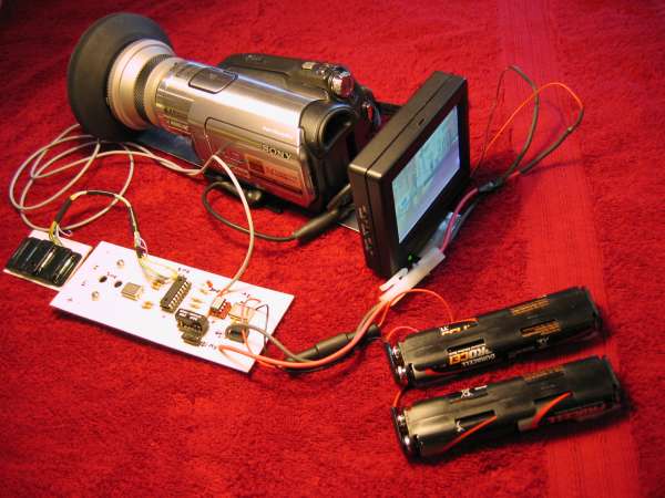
....and here is the kit all together.
DONATION You are more than welcome to download and use this information. If you need help then send me an email. If you would like to give a donation I would certainly appreciate it. All monies go to keep our diving club viable so that I can continue doing a sport I love so much.
DOWNLOADS |